


ok hello everyone at xtreme systems i have been reading your posts for a whiile and found them very intresting. I am making a project at college and thought why not make a cpu cooler block? crazy i no .
since im doing engineering i will have accese to many tools etc.
here is my plan so far using my own and this sites resorces
ok i have had a few ideas here they ok i have found some pics from this extreme website
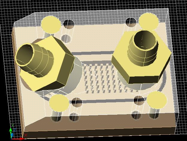
thats my measurments for where the holes will mount, my question is could i use an acrylic/lucite top, would that be a good choice or purely to just slap a copper sheet on the top once i have milled the copper out?
the image i drew with paint is one option i find very intresting since it shouldnt be that hard and it will be effective, the grey holes top and bottom are the holes to hold the lucite top on, held by screws once the copper has been tapped also i'll add a rubber washer, band around the rim just like the DD ones? what do you think any ideas tips?
and does anyone have a link to were i can buy that swiftech 6002 top? to hold it to the mobo either that or i will just make the lucite top
im pretty much confused how to mount it to the soc 939 athlon 64 mobo? any help or tips etc will be execellent because i know that DD have an overhang on the lucite top which would be nice if i could make that ?
also would buying a draper multi tool be worth it? 35£


 Reply With Quote
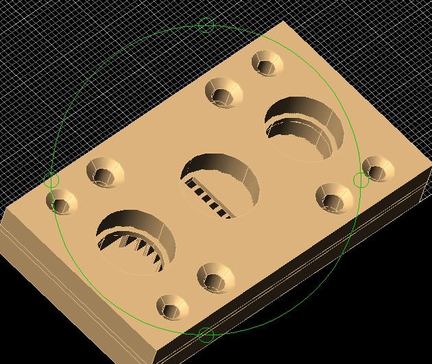


 .
.


Bookmarks