


As some of you know I decided to attempt to make a controller for a single system.
The goal was to make it open source, easy to build and cheap.
I decided on these specs:
0.2C steps -55 to +50C
Hardware settable condensor overtemperature set-point (activates an output) 0 -> 50
Hardware settable computer on set-point (activates an output) 0 -> -55
Hardware settable condensor temperature optimal point (for the fan control) 0 -> 50
Automatic fan throttling based on condensor temperature
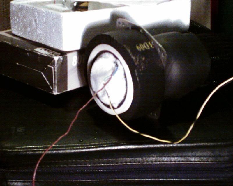
Thermistor sensors
LCD display
This is the first time I have used thermistors and so it was a learning curve. A thermocouple implementation would have been a lot easier but price of
thermocouples and the required CJC (cold junction compensation) ICs is to high - compared to the thermistor.
The system is simple. It works using 3 potentiometers to alter the set-points. You hold down the only button while turning it on and it goes to a visual
calibration mode. Turn the pots and when done release the button and the system moves on to a startup routien.
The startup loop checks your setpoint against the current evaporator temperature. A pulse is sent out a port to trigger something (ie a relay). During the
startup loop the fan is throttled and the condensor temperature is checked against the overtemperature setpoint.
Once the on set-point is reached the condensor and evaporator temperatures are shown. The fan and overtemperature checks are also polled.
Technical wise:
Implementation of the temperature calculation was done using a massive (1k) lookup table. This was calculated in excel using manufacture datasheets for the
thermistors I choose. Subsiquently I found there to be many thermistor manufacturers which supply software or precalculated tables (R/T curves).
It became apparent that with such a large temperature range the thermistor resistance values change dramtically on the low scale but very little on the
higher end. It was not possible to pickup the subtle change in voltage with the 10bit ADC on-chip. So I had to do some oversampling. The program uses an
effective 5bit oversample for an effective 15bit ADC.
The safety cutout is designed in the way that the controller has dedicated power. In an overtemperature situation the computer is first shutdown then the
other port triggers. I had intended for this trigger to shutdown the compressor. The fan control coming from the uC remains on. During the pull-down before
computer on, an overtemperature situation will not trigger the computer-on output. Only the cutout output.
This is a work in progress. I am entirely self taught for AVR assembler programming. I built my programmer as many of you will.
There are probably still some bugs I have not picked up on. This is were I would like your help.
I offer you a barebones setup. Customisable because there is fully commented code.
Enjoy this first installment.
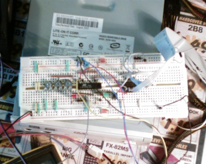
The prototype
Temperature testing against a thermocouple (borrowed)
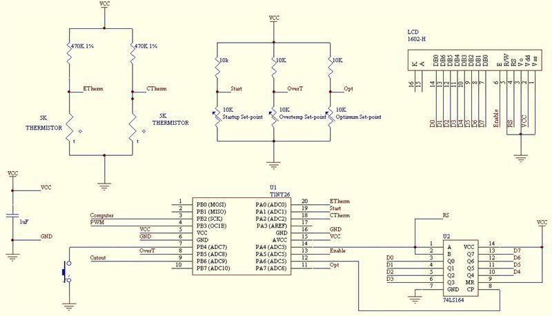
Basic schematic - for now at least
Code so far:
Some references for some light reading:
www.atmel.com
www.avrfreaks.net
http://avr-asm.tripod.com/
http://www.geocities.com/dinceraydin/lcd/intro.htm
http://www.sixca.com/resource/micro/index.html
ADC oversampling http://www.atmel.com/dyn/resources/p...ts/doc8003.pdf
AVRStudio http://www.atmel.com/dyn/products/to...p?tool_id=2725
Pony Prog http://www.lancos.com/prog.html
YAAP http://www.myplace.nu/avr/yaap/
STK200 dongle http://sbprojects.com/projects/stk200/stk200.htm
http://www.alldatasheet.com/datashee...I/74LS164.html
http://www.atmel.com/dyn/resources/p...ts/doc1477.pdf

 Reply With Quote
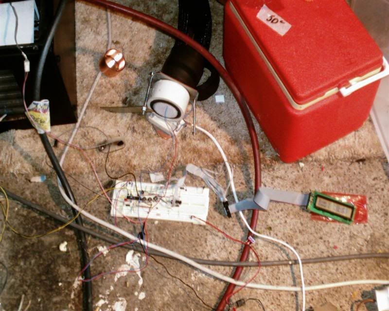


 Do you plan on making any yorself, for sale on any scale? or do you simply just want to design it? I have 3 SS DD units about to start, and probably more after that, I "could" be interested in a few.


 ) . Keep up the good work.

Bookmarks