Page 4 of 8 FirstFirst 1234567 ... LastLast
Results 76 to 100 of 177

Thread: PSU's 3.3v Rail directly connected to/as vdimm

  1. #76
    Xtreme X.I.P.
    Join Date
    Dec 2003
    Posts
    4,734
    Originally posted by Rub87
    Some time ago I also did the vdimm=3.3v mod on my NF7-s.. with one 256mb dimm installed, vdimm nicely follows +3.3v and vref=vtt/vbt is 0.5*vdimm.. but when 2 big dimms (2*512mb) are used cdimm drops to 3.2v (in bios) while +3.3v is still 3.4 even under load!, you would think, 3.2v is still good but the problem is that vref=vtt/vbt follows the vdimm thats displayed in bios so with big dimms vtt/vgt drops below 1.6 while vdimm is actually 3.4 because its directly connected to +3.3v line...

    What could be the cause of this? A to thin wire?

    Do you guys think I could fix this by using a thicker wire to every dimm..?

    Can't I directly put a wire from +3.3v to the point were bios reads the vdimm so bios would always see the correct vdimm..?

    Or build some kind'a regulator that cuts the vdimm always exactly in half to suplly vref and vtt/vbt..?

    sorry for my bad english
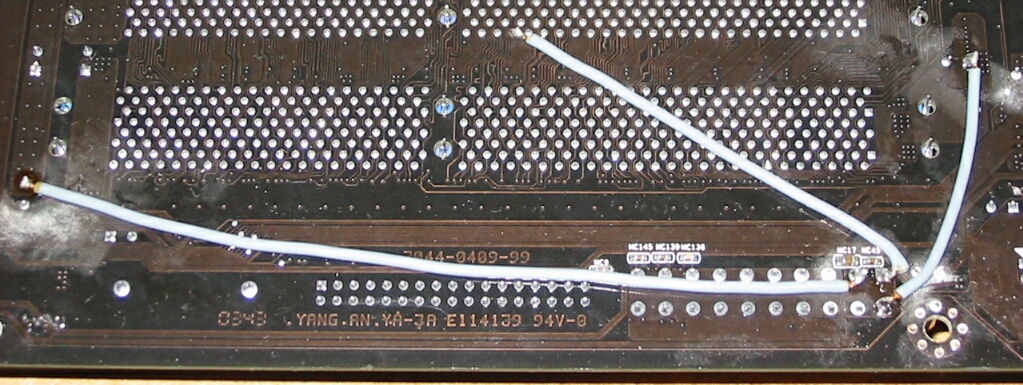
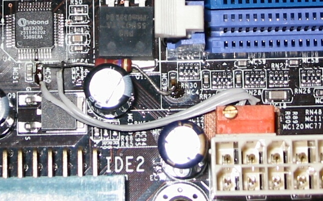
    i have almost identical situation except for i use thicker (gauge 24) with one solid copper strand.
    with vio=vdimm and vref=vtt voltmods:

    on idle voltages dont fluctuate
    vdimm = 3.60v
    3.3vio = 3.64v
    vref=vtt = 1.87v

    under heavy load (memtest+ or sandra mem benchmark)
    vdimm drops to 3.55v
    3.3vio = 3.64v
    vref=vtt drops to 1.80v

    before doing vref=vtt volmod vref was always 1.80v. vtt was at 1.87v and behaved same way as it does now. but i haven't seen any difference in mem stability, though.

    so actually i'm not worried about vdimm drop coz i would think it's normal but that vref=vtt not being 1/2 vdimm and its fluctuation sort of pisses me off...

    oh, and mem in DC config always makes vdimm and vtt drop lower that one stick in SC... no matter what vdimm mod i had...
    Last edited by bachus_anonym; 07-01-2004 at 08:04 AM.

  2. #77
    Xtreme Member
    Join Date
    Feb 2003
    Location
    Karlsruhe, Germany
    Posts
    122
    gomerpyle, i look on to my board and see your point in uncorrect. (crossed with pink)

    the (ddr1) dimm-socket pin-layout should be the same on all boards, and also on the two socked's above.
    so i red-marked (not all) points. i compared it on my other pics here postet and all is similar.
    really matters is the correct orientation of the pic/board, the socket has a longer and shorter "half".
    all the marked pins should (original) be connected together and with pin7 too --> all vdimm.
    please check this on your board and keep us informed.

    (your board... an amd?... looks very differend to my p4's)
    im relatively sure, red markers should be the right pins on ALL boards.


    edit1, add: (original) ; --> all vdimm
    edit2: add the pic with better viewable red dots. (link)
    edit3: removed the pic with poor readeble marked points for minimize the confusion...


    Last edited by Rio71; 07-10-2004 at 08:25 AM.

    - projekt seti-bench @ c4m under 2:00 ::: c4m 2500@3??? ::: 3.0E test'test... :-)
    - P4 2.4B @ 3300 IHS off :: 1,70V mod PAL8942 :: 4x256MB BH-5 DDR460 2-2-2-5-inf-64µs :: P4P800-Dlx
    R 8500 @ 295/295--> DVI --> EIZO 15" TFT :: Hitachi 180GXP :: HEC-300LR-PT :: 98SE/XP
    - C4m2000 @ 3350 :: 1,70V :: 36°C/51°C mod-Kühler :: DDR441 2-2-2-5 :: IS7-E :: IHS off
    - C4m1500 @ 3000 :: 1,7V MCX4000 + TMD :: DDR400 2-2-2-5-infinite-64µs :: 4GEA :: IHS off
    - PIII-S 1400 @ 1660 :: 1,45V :: 36°C/40°C/mod Volcano6cu :: TUSL2-C (Mod) (Bios@Mad) :: IHS on :: Bench
    - Laptop PIII 700@700 (100FSB/440BX) :: 256MB :: 18Gig Toshiba :: 4MB ATI :: 14,1" TFT :: Win98SE
    * Footnote: 90% of all computer problems can you find between chair and keyboard. ;-)

  3. #78
    Xtreme Member
    Join Date
    Feb 2003
    Location
    Karlsruhe, Germany
    Posts
    122
    Originally posted by Rub87
    .. but when 2 big dimms (2*512mb) are used cdimm drops to 3.2v

    What could be the cause of this? A to thin wire?

    Do you guys think I could fix this by using a thicker wire to every dimm..?
    yes, *lookatpic*, yes.
    use a thicker (and shorter) wire or better a couple of wires like my ic7 on page 3 and distribute the wires around the socked.
    i use 4x256mb and vdimm are stable as hell. (memtest86 #5)
    im remember right...?... bh-5 need 1 watt default per chip.
    on 4x256mb (same 2x512mb) 32w default, make 10 ampere !!!
    ... but this is for default vdimm 2,5v volt.

    i dont know about your bios and readings... but wat i can say is,
    dont trust the software, use an multimeter.

    - projekt seti-bench @ c4m under 2:00 ::: c4m 2500@3??? ::: 3.0E test'test... :-)
    - P4 2.4B @ 3300 IHS off :: 1,70V mod PAL8942 :: 4x256MB BH-5 DDR460 2-2-2-5-inf-64µs :: P4P800-Dlx
    R 8500 @ 295/295--> DVI --> EIZO 15" TFT :: Hitachi 180GXP :: HEC-300LR-PT :: 98SE/XP
    - C4m2000 @ 3350 :: 1,70V :: 36°C/51°C mod-Kühler :: DDR441 2-2-2-5 :: IS7-E :: IHS off
    - C4m1500 @ 3000 :: 1,7V MCX4000 + TMD :: DDR400 2-2-2-5-infinite-64µs :: 4GEA :: IHS off
    - PIII-S 1400 @ 1660 :: 1,45V :: 36°C/40°C/mod Volcano6cu :: TUSL2-C (Mod) (Bios@Mad) :: IHS on :: Bench
    - Laptop PIII 700@700 (100FSB/440BX) :: 256MB :: 18Gig Toshiba :: 4MB ATI :: 14,1" TFT :: Win98SE
    * Footnote: 90% of all computer problems can you find between chair and keyboard. ;-)

  4. #79
    c[_]
    Join Date
    Nov 2002
    Location
    Alberta, Canada
    Posts
    18,728
    Rio71 - AMD boards (nForce2's) have the dimm slots swapped end for end so they would be "upside down" to that pic I believe...

    I could be wrong, but if we comparred pics of the backsides or frontsides it would show if they are "backwards" or not.

    All along the watchtower the watchmen watch the eternal return.

  5. #80
    Xtreme Member
    Join Date
    Apr 2003
    Location
    Belgium
    Posts
    255
    OK,

    Probaly the wire is almost melted off

    When I find the energy to remove the evap from my mobo and the modo from my care I'll redo these mod and also mod my PSUs 3.3v rail..
    Venice 3500+ M @ 3ghz - Lanparty nf4 2 dimms dead - X800 - 512 Mb BH-5 - 1* WD360GD - 1*SP1213C - 1* Maxtor 6Y120L0

    Cpu: Prommy chilled

  6. #81
    c[_]
    Join Date
    Nov 2002
    Location
    Alberta, Canada
    Posts
    18,728
    If your vdimm mosfet is powered by the +3.3 rail you can solder from the supply source of the mosfet to the output leg and it will be effectively the same as 3.3 = vdimm.

    This usually means soldering from back of mosfet to right leg. Make sure to check with dmm.

    All along the watchtower the watchmen watch the eternal return.

  7. #82
    Registered User
    Join Date
    Jun 2004
    Posts
    9
    Originally posted by Rio71
    jalmir, thanks.
    i using here tsop winbond bh-5, bh-5 are bulletproof on 3,3v.
    i have an bundle infineon 6-a with relabeled bh-5/6 and working perfect.
    thx for the info!!!
    Life isn't like a box of chocolates...It's more like a jar of jalapenos... What you do today, might burn your @$$ tomorrow.

  8. #83
    Xtreme Member
    Join Date
    Feb 2003
    Location
    Karlsruhe, Germany
    Posts
    122
    Originally posted by STEvil
    Rio71 - AMD boards (nForce2's) have the dimm slots swapped end for end so they would be "upside down" to that pic I believe...
    I could be wrong, but if we comparred pics of the backsides or frontsides it would show if they are "backwards" or not.
    yes, i noticed this as i painted the red dots --> longer/shorter.
    for comparing with other boards, i load pic in irvanview and rotate it.
    but the space between the pairs of sockets are nice for adding cooling parts on ram's.
    on my p4-boards the pairs of sockets are close together, no space between.
    the layout is also different...

    - projekt seti-bench @ c4m under 2:00 ::: c4m 2500@3??? ::: 3.0E test'test... :-)
    - P4 2.4B @ 3300 IHS off :: 1,70V mod PAL8942 :: 4x256MB BH-5 DDR460 2-2-2-5-inf-64µs :: P4P800-Dlx
    R 8500 @ 295/295--> DVI --> EIZO 15" TFT :: Hitachi 180GXP :: HEC-300LR-PT :: 98SE/XP
    - C4m2000 @ 3350 :: 1,70V :: 36°C/51°C mod-Kühler :: DDR441 2-2-2-5 :: IS7-E :: IHS off
    - C4m1500 @ 3000 :: 1,7V MCX4000 + TMD :: DDR400 2-2-2-5-infinite-64µs :: 4GEA :: IHS off
    - PIII-S 1400 @ 1660 :: 1,45V :: 36°C/40°C/mod Volcano6cu :: TUSL2-C (Mod) (Bios@Mad) :: IHS on :: Bench
    - Laptop PIII 700@700 (100FSB/440BX) :: 256MB :: 18Gig Toshiba :: 4MB ATI :: 14,1" TFT :: Win98SE
    * Footnote: 90% of all computer problems can you find between chair and keyboard. ;-)

  9. #84
    Xtreme Enthusiast
    Join Date
    Nov 2003
    Location
    VIENNA
    Posts
    632
    Excellent rio! thanks alot
    Did your VTT mod require cutting?
    Ow an which of the grey wires are needed, and for what are the other wires?

    Originally posted by Rio71
    vtt should (must) be the half of vdimm.
    this is for termination of memory-bus (like scsi etc...)
    with uncorrect vtt, stable speed is lower.


    here the mod for ic7.
    no lifting or cutting is needed... simply connect one of the grey wire... is enough and doing the "same" as one.
    3 is for better distribution... high-end


    second pic is my vtt-mod on ic7...


    Overclocking made in Austria

  10. #85
    Registered User
    Join Date
    Jun 2004
    Posts
    9

    Talking

    Thanks Rio71 for that cool and easy mod...

    I translated it in frensh (I'm frensh canadian... I know, those are my two big flaws!!! ) and post it on a big frensh OC forum

    This mod is very apreciated there!

    Thaks again and keep up the good work!!!


    Jal
    Life isn't like a box of chocolates...It's more like a jar of jalapenos... What you do today, might burn your @$$ tomorrow.

  11. #86
    Xtreme Member
    Join Date
    Feb 2003
    Location
    Karlsruhe, Germany
    Posts
    122
    Did your VTT mod require cutting?
    Ow an which of the grey wires are needed, and for what are the other wires?
    yes, im cutting the trace on backside.
    read all the very good info in the vtt-treads on this great forum.

    the middle wire connected direktly to the dimm.
    other both are connected to the dimm-stabilizing-cap's, is possibly easyer to soldering for ppl have not so fine tools or hands ;-)
    every of the grey wires doing the same, more is better.
    (look at the atx-plug, 3x orange and 1+2 yellow and lots of black )

    - projekt seti-bench @ c4m under 2:00 ::: c4m 2500@3??? ::: 3.0E test'test... :-)
    - P4 2.4B @ 3300 IHS off :: 1,70V mod PAL8942 :: 4x256MB BH-5 DDR460 2-2-2-5-inf-64µs :: P4P800-Dlx
    R 8500 @ 295/295--> DVI --> EIZO 15" TFT :: Hitachi 180GXP :: HEC-300LR-PT :: 98SE/XP
    - C4m2000 @ 3350 :: 1,70V :: 36°C/51°C mod-Kühler :: DDR441 2-2-2-5 :: IS7-E :: IHS off
    - C4m1500 @ 3000 :: 1,7V MCX4000 + TMD :: DDR400 2-2-2-5-infinite-64µs :: 4GEA :: IHS off
    - PIII-S 1400 @ 1660 :: 1,45V :: 36°C/40°C/mod Volcano6cu :: TUSL2-C (Mod) (Bios@Mad) :: IHS on :: Bench
    - Laptop PIII 700@700 (100FSB/440BX) :: 256MB :: 18Gig Toshiba :: 4MB ATI :: 14,1" TFT :: Win98SE
    * Footnote: 90% of all computer problems can you find between chair and keyboard. ;-)

  12. #87
    Registered User
    Join Date
    Jun 2004
    Location
    British Columbia
    Posts
    67
    I'm confused about this mod. I read it before and thought it was 3.3v --> solder to pin 7 on dimm

    but I see thats just to measure the vdimm


    These pics show different things. Is this mod different on different mobos?

    If not, what pin do I connect the 3.3v? And I'm only using one dimm.

    If its always different, what do I do to find where to connect the 3.3v? Sorry if I missed the explaination or I'm being totaly stupid here. I'm just confused right now

  13. #88
    Xtreme Member
    Join Date
    Apr 2003
    Location
    Belgium
    Posts
    255
    3.3v to pin 7, simple as what!,

    Pin 7 is vdimm, thats why you need to measure vdimm on pin7, and when you connect 3.3v to pin 7, your vdimm wil be what your 3.3v rail is.. better double check if you have pin 7 because on some mobos the dimms are turned 180°...
    Venice 3500+ M @ 3ghz - Lanparty nf4 2 dimms dead - X800 - 512 Mb BH-5 - 1* WD360GD - 1*SP1213C - 1* Maxtor 6Y120L0

    Cpu: Prommy chilled

  14. #89
    Registered User
    Join Date
    Jun 2004
    Location
    British Columbia
    Posts
    67
    thats what I thought, but how come it looks like the wires are going to something else in all these pics? Like near the middle on the long side of the dimm, like the 4th pin over from the middle you can see just above, or in other pics its some other pin near the middle.


  15. #90
    Xtreme Member
    Join Date
    Apr 2003
    Location
    Belgium
    Posts
    255
    Those pins are also vdimm.. here you can see which pins are vdimm...
    Venice 3500+ M @ 3ghz - Lanparty nf4 2 dimms dead - X800 - 512 Mb BH-5 - 1* WD360GD - 1*SP1213C - 1* Maxtor 6Y120L0

    Cpu: Prommy chilled

  16. #91
    Registered User
    Join Date
    Jun 2004
    Location
    British Columbia
    Posts
    67
    so do I randomly connect the 3.3 to one?
    SN45G (FN45 v2.0)
    XP-M 2500+
    1x512 Mushkin PC3500 level 1 **BH5**
    MSI GF4 Ti4200VTP 128MB/4x
    200CFM 21W SUNON 120MM
    **VMODS:**
    -vdimm = 3.3v
    -to do: vdd, vcore

  17. #92
    Xtreme Member
    Join Date
    Apr 2003
    Location
    Belgium
    Posts
    255
    Yup, you can also connect the 3.3v rail to the vdimm elco but the pin method works also!
    Venice 3500+ M @ 3ghz - Lanparty nf4 2 dimms dead - X800 - 512 Mb BH-5 - 1* WD360GD - 1*SP1213C - 1* Maxtor 6Y120L0

    Cpu: Prommy chilled

  18. #93
    Xtreme Member
    Join Date
    Feb 2003
    Location
    Karlsruhe, Germany
    Posts
    122

    ... thats it.

    yes... all like Rub87 say.

    - projekt seti-bench @ c4m under 2:00 ::: c4m 2500@3??? ::: 3.0E test'test... :-)
    - P4 2.4B @ 3300 IHS off :: 1,70V mod PAL8942 :: 4x256MB BH-5 DDR460 2-2-2-5-inf-64µs :: P4P800-Dlx
    R 8500 @ 295/295--> DVI --> EIZO 15" TFT :: Hitachi 180GXP :: HEC-300LR-PT :: 98SE/XP
    - C4m2000 @ 3350 :: 1,70V :: 36°C/51°C mod-Kühler :: DDR441 2-2-2-5 :: IS7-E :: IHS off
    - C4m1500 @ 3000 :: 1,7V MCX4000 + TMD :: DDR400 2-2-2-5-infinite-64µs :: 4GEA :: IHS off
    - PIII-S 1400 @ 1660 :: 1,45V :: 36°C/40°C/mod Volcano6cu :: TUSL2-C (Mod) (Bios@Mad) :: IHS on :: Bench
    - Laptop PIII 700@700 (100FSB/440BX) :: 256MB :: 18Gig Toshiba :: 4MB ATI :: 14,1" TFT :: Win98SE
    * Footnote: 90% of all computer problems can you find between chair and keyboard. ;-)

  19. #94
    Registered User
    Join Date
    Jun 2004
    Location
    British Columbia
    Posts
    67
    yay, success here


    but i did it on my sn45g v2 mobo (notorious for dieing if you change the vdimm)
    happy me, everything works
    time for vdd mod now to get past the chipset brickwall ~230fsb
    running for now @ 220fsb / 2-2-2-11 on my stick of 512 mushkin level one pc3500
    SN45G (FN45 v2.0)
    XP-M 2500+
    1x512 Mushkin PC3500 level 1 **BH5**
    MSI GF4 Ti4200VTP 128MB/4x
    200CFM 21W SUNON 120MM
    **VMODS:**
    -vdimm = 3.3v
    -to do: vdd, vcore

  20. #95
    Xtreme Member
    Join Date
    Sep 2003
    Location
    Denmark
    Posts
    298
    RIO I tried the mod on my AMD mobo. Measured where PIN7 was 0-0,3 ohm to a dimm pin on the back and soldered 3.3v direct to that pin, but no go. The Dimm says standard 2.62v. Then I measured the PIN7 to ground which says 1.30v.

    Please correct me if I've done something wrong here.
    Brian Hermansen...benching with Jacob Hansen
    3DMark01 42400 | Aquamark3 104762 | PiFast 34.58
    Running chilly1 cascade

  21. #96
    Xtreme Member
    Join Date
    Apr 2003
    Location
    Belgium
    Posts
    255
    How can you measure 1.3v @ pin7 when that pin is connected to your 3.3v rail?
    Venice 3500+ M @ 3ghz - Lanparty nf4 2 dimms dead - X800 - 512 Mb BH-5 - 1* WD360GD - 1*SP1213C - 1* Maxtor 6Y120L0

    Cpu: Prommy chilled

  22. #97
    Fused
    Join Date
    Dec 2003
    Location
    Malaysia
    Posts
    2,769


  23. #98
    Registered User
    Join Date
    Jun 2004
    Location
    British Columbia
    Posts
    67
    I didn't take a pic, but on my mobo all the vdimm pins I could differentiate from the others; they were a little smaller than all the others.
    SN45G (FN45 v2.0)
    XP-M 2500+
    1x512 Mushkin PC3500 level 1 **BH5**
    MSI GF4 Ti4200VTP 128MB/4x
    200CFM 21W SUNON 120MM
    **VMODS:**
    -vdimm = 3.3v
    -to do: vdd, vcore

  24. #99
    Xtreme Member
    Join Date
    Feb 2003
    Location
    Karlsruhe, Germany
    Posts
    122

    i dont know

    Originally posted by GomerPyle
    RIO I tried the mod on my AMD mobo. Measured where PIN7 was 0-0,3 ohm to a dimm pin on the back and soldered 3.3v direct to that pin, but no go. The Dimm says standard 2.62v. Then I measured the PIN7 to ground which says 1.30v.

    Please correct me if I've done something wrong here.
    ... again like Rub87 say...

    i think your have an (thinking) sequence error.
    your measured voltage seems to be vtt. (half vdimm)

    please make absolutely sure you have the PIN7.
    look for the stamping 1 on plastic and count from here... watch the pic at page1...

    can you add an close-view pic ?


    - projekt seti-bench @ c4m under 2:00 ::: c4m 2500@3??? ::: 3.0E test'test... :-)
    - P4 2.4B @ 3300 IHS off :: 1,70V mod PAL8942 :: 4x256MB BH-5 DDR460 2-2-2-5-inf-64µs :: P4P800-Dlx
    R 8500 @ 295/295--> DVI --> EIZO 15" TFT :: Hitachi 180GXP :: HEC-300LR-PT :: 98SE/XP
    - C4m2000 @ 3350 :: 1,70V :: 36°C/51°C mod-Kühler :: DDR441 2-2-2-5 :: IS7-E :: IHS off
    - C4m1500 @ 3000 :: 1,7V MCX4000 + TMD :: DDR400 2-2-2-5-infinite-64µs :: 4GEA :: IHS off
    - PIII-S 1400 @ 1660 :: 1,45V :: 36°C/40°C/mod Volcano6cu :: TUSL2-C (Mod) (Bios@Mad) :: IHS on :: Bench
    - Laptop PIII 700@700 (100FSB/440BX) :: 256MB :: 18Gig Toshiba :: 4MB ATI :: 14,1" TFT :: Win98SE
    * Footnote: 90% of all computer problems can you find between chair and keyboard. ;-)

  25. #100
    Registered User
    Join Date
    Jun 2004
    Location
    Belgium, Earth
    Posts
    4
    I've tried this mod on my NF7-S 2.0 and it just won't boot with the wire connected. When i desolder the wire it works like charm.
    Do I need to mod my psu (zalman 300W) or what?
    I have the same mods as on this pic, except the cpu stuff: http://www.xtremesystems.org/forums/...&postid=481318

    I've got the same problem with an Abit KX7-333R...
    Last edited by Arioch; 07-08-2004 at 03:01 PM.

Page 4 of 8 FirstFirst 1234567 ... LastLast

Bookmarks

Bookmarks

Posting Permissions

  • You may not post new threads
  • You may not post replies
  • You may not post attachments
  • You may not edit your posts
  •